


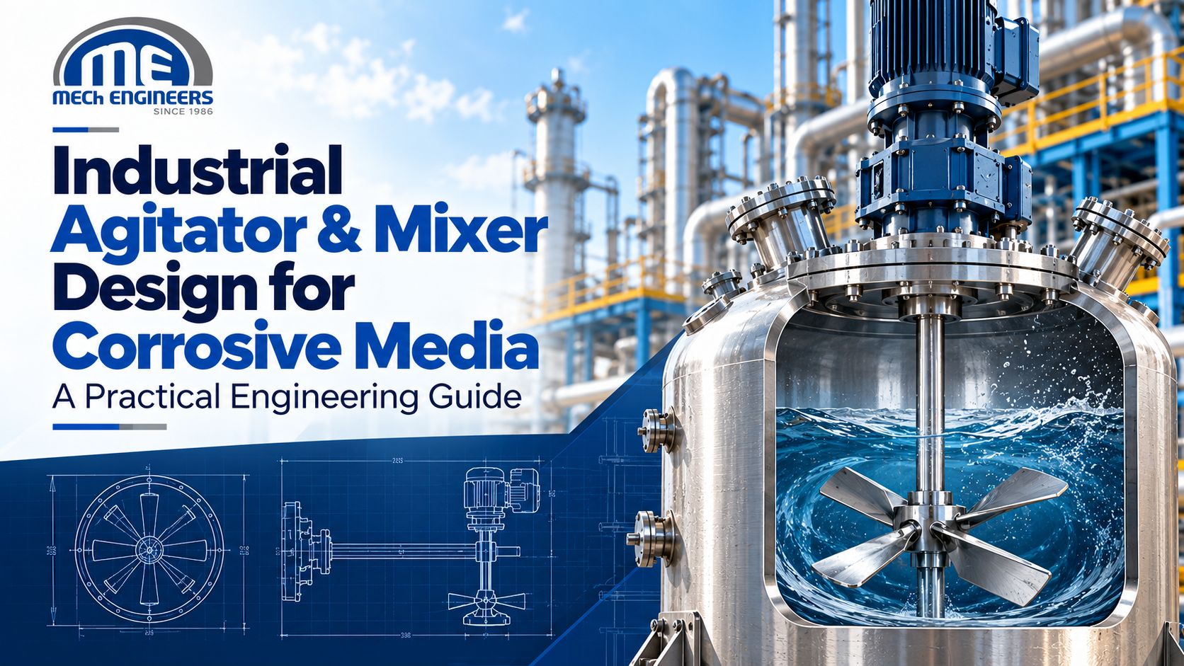
Industrial Agitator & Mixer Design for Corrosive Media: A Practical Engineering Guide
Designing an agitator for aggressive chemicals involves two separate engineering problems that have to be solved together. The first is hydraulic: what flow, shear, and circulation does the process need? The second is material and mechanical: what will survive contact with the fluid, solids, temperature, and seal environment? Industrial agitator and mixer design for corrosive media reconciles the two. An impeller can be ideal for the mixing duty and wrong for the chemistry, and a corrosion-resistant alloy can be perfectly chosen and still deliver poor mixing.
This guide sets out the decisions in the order an engineer would make them, and what a manufacturer needs to know before recommending a configuration.
Why Corrosive Media Changes Agitator Design
An agitator is not a single wetted part. The shaft, impeller, fasteners, any shaft-to-impeller coupling, the vessel wall and internals, the seal faces and elastomers, and sometimes bearings are all potentially exposed. Each fails differently. A shaft can be attacked at the liquid-vapour interface, where conditions differ from the fully immersed region. A seal can fail from chemical attack on an elastomer even when every metal part is sound.
Corrosion resistance is therefore a system property. Selecting an alloy for the impeller and leaving the seal, fasteners, and shaft to default choices leaves the weakest component to set the service life.
Process Data Required Before Designing an Agitator
The data needed depends on the duty, and not every item applies to every job. Blending two miscible low-viscosity liquids needs little information about solids. A slurry or gas-liquid duty needs much more.
Information that usually shapes the design:
- Vessel: geometry, working and operating volume, liquid level range, internals, nozzle layout, heating or cooling surfaces.
- Fluid: density, viscosity (and how it changes with temperature or conversion), chemical composition, concentration, contaminants.
- Conditions: temperature, pressure or vacuum, batch or continuous operation, the operating cycle, and cleaning chemicals and methods.
- Duty: the mixing objective (blending, suspension, dispersion, gas-liquid contact, heat transfer), the number of phases, and, where relevant, solids concentration and particle characteristics.
- Site: hazardous-area classification and applicable project specifications.
Chemical composition and concentration belong at the top of this list, not at the bottom. They govern materials and sealing as much as viscosity governs the impeller.
Industrial Agitator & Mixer Design for Corrosive Media: How the Decisions Connect
The sequence matters. The process duty and fluid properties, together with vessel geometry, point toward an impeller family and diameter range. Speed and power follow from that choice and from the required flow or shear. Power and speed, together with the shaft length and the loads on it, drive shaft design. Materials of construction and the sealing arrangement then have to be compatible with the chemistry at the operating conditions, and they also feed back: a material with different strength or a lining that thickens a section may change what is mechanically feasible.
Two practical consequences follow. First, material selection should not come first, because a hydraulically unsuitable agitator in an excellent alloy is still unsuitable. Second, the design is iterative. A late change of material or seal type can alter shaft dimensions, bearing arrangement or the vessel nozzle, so it is cheaper to settle the chemistry and conditions before detailed design starts.
No numerical rule of thumb for speed, power or tip speed is given here. These values depend on the impeller, vessel and fluid, and should come from the manufacturer’s design for your specific data.
Material Selection for Corrosive Chemical Service
The main material families are austenitic stainless steels, duplex and super-duplex stainless steels, nickel-based alloys, titanium and titanium alloys, and carbon steel with a non-metallic lining or coating. None is universally suitable. Each has environments where it performs well and environments where it fails quickly.
Chloride-bearing service shows why grade selection cannot be reduced to “stainless steel”. According to the Specialty Steel Industry of North America, no stainless steel grade is totally immune to chloride stress corrosion cracking, though resistance varies considerably by family, and susceptibility rises with temperature, chloride content, lower pH and tensile stress. A separate source notes that standard 304/304L and 316/316L grades are among the most susceptible, and that higher nickel content or duplex and ferritic grades improve resistance. This is a single failure mode in a single environment type. Other chemistries, such as reducing acids or strongly oxidising media, bring entirely different material questions. Manufacturers show that the practical answer varies by application. EKATO’s flue-gas desulfurization side-entry agitators, for example, list acid-resistant steels, nickel-base alloy, duplex and super-duplex steels as wetted material options, with the choice depending on the plant’s conditions. That is manufacturer-specific information for one application, not a general rule.
Final material selection needs a process-specific compatibility assessment: chemical identity, concentration, temperature, contaminants (including chlorides), oxidising or reducing character, solids, local velocity, exposure time and cleaning conditions. pH alone is not a selection parameter. Generic compatibility tables are a starting point to be checked against supplier data or testing.
Corrosion vs Erosion in Mixing Equipment
Corrosion is chemical or electrochemical deterioration of the material. Erosion is material loss from fluid motion, suspended particles or other mechanical effects. They have different causes, different evidence on inspection, and different remedies.
They also interact. In a corrosive slurry, particle impact can remove a protective surface film or coating, exposing fresh material to attack, so the combined loss can exceed what either mechanism would cause alone. Local conditions matter: impeller tips and leading edges, regions of high local velocity, and surfaces where solids concentrate are more exposed than the bulk fluid suggests.
This is why an alloy chosen from a static corrosion table can underperform in a mixing vessel. The table describes the chemistry, not the flow. Service life figures should come from the manufacturer’s experience with comparable duty, not from general estimates.
Selecting the Right Impeller for the Mixing Duty
Impeller selection starts from the process result required, not from the chemistry.
- Propeller and hydrofoil (axial-flow) impellers generate bulk circulation and are commonly used for blending and for suspending solids where flow throughout the vessel matters more than local shear.
- Pitched-blade turbines combine axial and radial flow, giving a compromise that suits several duties.
- Radial-flow turbines, including the Rushton type, produce higher local shear and are associated with gas dispersion and some liquid-liquid duties.
- High-shear and dispersing impellers serve dispersion and rapid wetting duties.
- Anchor and helical-ribbon designs are used for high-viscosity fluids, where the impeller must move material near the wall.
One manufacturer-based example shows how duty drives choice: a combined unit may use a high-speed disperser alongside a slow anchor agitator on separate shafts, because the duties differ (ROSS describes a 316 stainless steel vessel with a high-speed disperser and a slow two-wing anchor agitator in one unit). No single type is universally best. The right impeller is the one that delivers the required result in that vessel with that fluid, and it then has to be built from a material that survives the service.
Shaft and Mechanical Design Considerations
Corrosion resistance is one requirement of a shaft among several. It must carry torque, resist bending from hydraulic loads on the impeller, and limit deflection at the seal and at the bottom of the shaft. For long shafts, critical-speed considerations apply, and cyclic loading raises fatigue questions. The connection between shaft and impeller is a design item in its own right, since it is a fastened joint exposed to the process and a potential crevice.
Manufacturers state this explicitly in their own context. EKATO describes its FGD agitators as designed for fatigue strength based on rated motor power and maximum dynamic loads. The principle is general; the specifics are not. Shaft diameter and length must come from a calculation on the actual design, not from a rule.
Mechanical Seals and Sealing Systems
In corrosive service the seal is frequently the component that determines reliability. It has to withstand the process fluid on its faces and elastomers, operate at the vessel pressure and temperature, handle shaft movement, and be maintainable.
Several arrangements are in use. Single-acting seals have one sealing surface and are simpler. Double-acting arrangements add a second sealing surface and are used with a barrier or buffer system (EKATO describes single-acting seals as having one sealing surface and double-acting seals as having two). A barrier or buffer system adds equipment, instrumentation and maintenance, but isolates the process fluid from the atmosphere. Seal-face materials and elastomers need their own compatibility check against the process fluid, separate from the metal selection. Dry-running capability matters if the vessel can be operated or emptied with the seal unwetted.
Magnetically coupled drives are one alternative. Manufacturer documentation describes them as having no shaft penetrating the tank, and therefore no mechanical seal (SPX Lightnin, for its MagMixer series). That removes a conventional dynamic shaft penetration. It does not make the system universally leak-free or suitable for every duty: torque limits, bearings that run in the process fluid, containment-shell materials and vessel configuration all need to be assessed for the application.
Linings and Coatings for Corrosive Service
Where alloys are impractical or uneconomic, a non-metallic lining or coating on a steel substrate is an alternative. Candidates include polypropylene, PVC, ECTFE, PTFE, and rubber or ebonite. Glass lining is a distinct, widely used option for agitators in glass-lined reactors.
No lining is suitable by default for a given chemical. Selection depends on chemical compatibility, temperature, permeation, abrasion and mechanical damage, adhesion, fabrication constraints and operating conditions. Rubber-coated shafts and impellers are used in abrasive, corrosive, high-solids duties, as in EKATO’s compact agitators with rubber-coated shafts and impellers for abrasive and corrosive products with high solid contents. The vulnerability of any lining is damage: a breach exposes the substrate, so inspection access and handling during installation matter as much as the lining itself.
Integrating the Agitator with the Vessel
The agitator cannot be designed independently of the vessel. Diameter, liquid height, bottom shape, internals, nozzle positions, coils and jackets all shape the flow pattern the impeller produces. An impeller position that works in one geometry may leave dead zones in another. Shaft position and mounting also determine how the shaft is supported and how far it extends into the liquid.
Reactor type matters to the agitator. In glass-lined systems, for example, Pfaudler states that glass-lined mixing systems are in most cases top-entry, without bottom bearings, with baffles installed on other nozzles. That describes one manufacturer’s typical arrangement and should not be read as a rule for all glass-lined reactors; the agitator has to be compatible with the specific reactor design and duty. Stainless steel reactors offer a wider range of configurations, and the same duty-first logic applies.
Baffles and Flow Pattern
Baffles break up swirling flow and convert rotation into top-to-bottom circulation. Whether they are needed depends on the vessel geometry, fluid properties and impeller type. Low-viscosity fluids in an unbaffled vessel tend to rotate as a mass; high-viscosity designs such as anchors are commonly used without them. Not every vessel needs baffles, and in corrosive service baffles are additional wetted surfaces that must be made of a suitable material and may be a source of crevices or erosion.
Special Considerations for Corrosive Slurries
Solids change the problem in several ways. Abrasion wears impeller edges and the shaft. Corrosion and erosion can reinforce each other. Suspension duty may require higher local velocities, which raise wear exposure, while insufficient suspension lets solids settle and cause uneven concentration. The seal is particularly exposed: particles at the seal faces can shorten life, so seal protection, such as flushing or barrier fluid, and maintenance access are design requirements. EKATO’s FGD seal, for instance, is described as a cartridge-type seal designed for highly abrasive and corrosive media, with a shut-off device allowing seal service without emptying the tower.
Particle size and solids loading limits are not stated here, because they depend on the specific impeller, material, and duty.
Common Mistakes in Corrosive-Media Agitator Design
- Selecting material by pH alone. Chemical identity, concentration, temperature and contaminants such as chlorides decide suitability.
- Ignoring concentration or temperature. The same chemical can be benign in one condition and aggressive in another, including during cleaning or upset conditions.
- Treating corrosion resistance and mixing performance as one problem. They need separate decisions.
- Choosing the impeller before defining the mixing objective.
- Checking metals but not seal faces and elastomers.
- Overlooking abrasive solids when the corrosion data comes from a clear liquid.
- Designing the agitator without the vessel, including internals and nozzles.
- Using generic tables without application-specific verification.
- Giving the manufacturer incomplete process data, which forces assumptions that end up in the equipment.
Agitator Specification / RFQ Checklist
What to give an agitator manufacturer before requesting a design:
- Vessel dimensions, internals, nozzle layout and working volume
- Fluid density, viscosity and its variation with temperature
- Chemical composition and concentration, including contaminants and chlorides
- Operating and design temperature, pressure or vacuum
- Mixing objective and required result
- Solids content and particle description, where applicable
- Preferred or mandated materials, and any lining requirement
- Seal requirements and barrier fluid availability
- Hazardous-area classification
- Batch or continuous operation and the operating cycle
- Cleaning chemicals and methods
- Applicable project standards and specifications
When to Consult an Agitator Manufacturer
Agitator selection is application-specific, and a manufacturer can only recommend a configuration once the process data above is available. Consult early when the fluid combines several aggressive factors, when solids are present, when sealing options are constrained, or when the vessel is being designed at the same time as the agitator. MECh Engineers designs and manufactures process plant equipment, including chemical reactors, to customer process requirements. If you are specifying an agitator for corrosive service, you can contact MECh Engineers with your process data to discuss the application.
Conclusion
Industrial agitator and mixer design for corrosive media works when the mixing duty, vessel geometry, materials, shaft and seal are treated as one system and settled in a sensible order: duty first, then mechanics, then chemistry-driven materials and sealing, verified against the actual process conditions. Complete process data at the start prevents most of the mistakes listed above.