



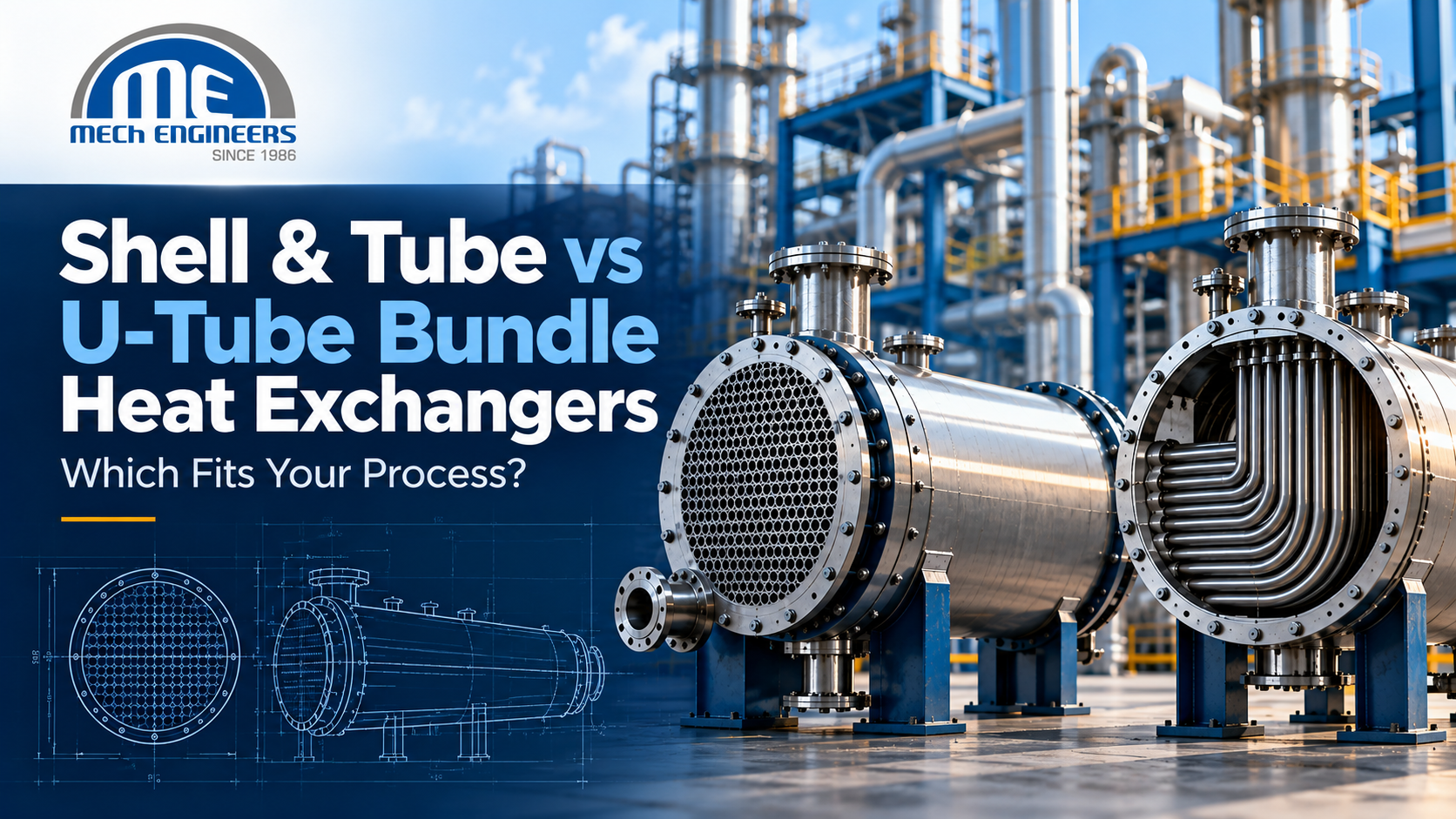
Shell & Tube vs U-Tube Bundle Heat Exchangers: Which Fits Your Process?
Heat exchangers sit at the center of most industrial processes, moving thermal energy between fluids so that reactions, separations, and utility systems run at the temperatures they were designed for. Because a poorly matched exchanger configuration can mean unplanned shutdowns, excessive cleaning cycles, or premature tube failure, the choice of configuration deserves the same scrutiny as the choice of materials or duty rating.
Among shell and tube exchangers, one of the most common early decisions is whether to specify a fixed-tubesheet design or a U-tube bundle. It’s worth being precise about the terminology here: a U-tube heat exchanger is not a different category of equipment from a shell and tube heat exchanger — it is a configuration within that family, distinguished mainly by how the tube bundle is built and how it handles thermal expansion, cleaning, and maintenance access. The right choice depends on process conditions, temperature differential, fouling behavior, cleaning requirements, materials, and mechanical design constraints, not on a generic preference for one design over the other.
What Is a Shell and Tube Heat Exchanger?
A shell and tube heat exchanger consists of a cylindrical shell containing a bundle of tubes. One fluid flows through the inside of the tubes (the tube side); the other flows around the outside of the tubes, within the shell (the shell side). Heat transfers across the tube walls between the two fluids without them mixing.
The tube bundle is held in place by tubesheets at the ends, which also separate the tube-side and shell-side fluids, and by baffles spaced along the shell length. Baffles direct the shell-side fluid across the tube bundle rather than straight through it, which improves heat transfer and provides mechanical support that helps limit tube vibration.
Shell and tube construction is widely used across chemical processing, petrochemical, refining, pharmaceutical, fertilizer, and power generation applications because the geometry scales to a wide range of pressures, temperatures, and duties, and because the equipment is built to well-established codes — principally the TEMA Standard for mechanical design and, where applicable, the ASME Boiler and Pressure Vessel Code, Section VIII, for pressure-retaining parts.
Within this family, TEMA nomenclature identifies the specific configuration using a three-letter code for the front head, shell type, and rear head — for example, AEL for a fixed-tubesheet design or BEU for a U-tube design. Fixed-tubesheet and U-tube construction are two of the ways the rear head and tube bundle can be arranged; a third common approach uses a floating head.
What Is a U-Tube Bundle Heat Exchanger?
In a U-tube bundle, the tubes are bent into a U shape (or hairpin shape) rather than run straight through the shell. Both ends of every tube terminate at the same tubesheet, at the front of the exchanger. The bend at the far end is unsupported by any second tubesheet — it floats freely inside the shell.
This single-tubesheet geometry is the defining feature of U-tube construction, and it’s the reason the design behaves differently from a fixed-tubesheet exchanger when the tube-side and shell-side fluids operate at significantly different temperatures. Because only one end of each tube is rigidly fixed, the tube is free to expand or contract along its length independently of the shell, without transmitting that expansion into a second, fixed tubesheet.
That doesn’t mean thermal expansion becomes a non-issue. Differential expansion within the bundle itself — between tubes at different radial positions, or between the tubes and the shell — still needs to be accounted for in the mechanical design, and other TEMA-recognized approaches, such as a floating head or an expansion joint on a fixed-tubesheet shell, exist specifically to manage expansion in configurations where a U-tube bundle isn’t the appropriate choice.
Shell & Tube vs U-Tube Heat Exchanger: Key Differences
| Parameter | Fixed-Tubesheet Shell & Tube | U-Tube Heat Exchanger |
| Tube configuration | Straight tubes, two tubesheets | U-shaped tubes, single tubesheet |
| Thermal expansion | May require an expansion joint under large temperature differentials | Tubes expand/contract independently of the shell; no expansion joint typically needed |
| Tube-side cleaning | Tube ends accessible for mechanical cleaning by removing end covers | Straight tube runs accessible; U-bend region cannot be mechanically cleaned |
| Shell-side cleaning | Generally not possible — tubesheets are welded to the shell | Bundle is removable, allowing shell-side mechanical cleaning |
| Tube replacement | Depends on construction and access | Possible but more complex due to the return-bend geometry |
| Fouling considerations | Route fouling fluid where cleaning access exists (tube side) | Route clean, non-fouling fluid through the tube side, since the U-bend limits cleaning |
| Typical cost driver | Expansion joint (if required) adds cost | Often the lowest-cost removable-bundle option for a given duty, per general industry practice |
| Common TEMA designators | AEL, BEM, NEN, among others | AEU, BEU |
This table reflects general engineering tendencies, not universal rules. Actual equipment design depends on the specific service conditions, applicable codes and standards, and the manufacturer’s mechanical and thermal engineering for that project.
Thermal Expansion — Where U-Tube Construction Can Be Valuable
When the tube-side and shell-side fluids operate at markedly different temperatures, the tubes and the shell try to expand by different amounts. In a fixed-tubesheet exchanger, where both ends of every tube are rigidly connected to tubesheets that are themselves welded to the shell, that mismatch generates longitudinal stress in the tubes, the tubesheets, and the shell-to-tubesheet joint. Under severe service conditions, this can become the dominant reliability concern for the unit.
One established way to relieve that stress in a fixed-tubesheet design is to add a shell-side expansion joint — a flexible element that absorbs some of the differential movement. It works, but it adds cost and introduces its own considerations around fatigue life and mechanical robustness.
U-tube construction offers a different path: because only one end of each tube is fixed, the tube can grow or shrink along its own length without pulling against a second tubesheet. This is the central engineering reason U-tube bundles are specified in high-temperature-differential services, and it is why they are frequently the default choice for equipment such as steam-heated reboilers, where the two fluids can be far apart in temperature.
It would be an overstatement to say U-tube construction eliminates thermal-stress concerns entirely. Differential expansion between individual tubes, tube-to-tubesheet joint integrity, and overall mechanical design still require proper engineering analysis for the specific service — the U-tube geometry manages one particular expansion problem well; it doesn’t remove the need for that analysis.
Fouling and Cleaning Considerations
Cleaning access is arguably the single most consequential trade-off between these two configurations, and it works in opposite directions on the tube side versus the shell side.
In a fixed-tubesheet exchanger, the tube ends are accessible once the end covers or bonnets are removed, so tube-side mechanical cleaning — running a lance or brush through each tube — is generally practical. The shell side is a different story: because the tubesheets are welded to the shell, the bundle cannot be withdrawn, so shell-side mechanical cleaning and inspection are limited or unavailable.
A U-tube bundle inverts part of that picture. The bundle can be pulled from the shell, which makes shell-side mechanical cleaning and inspection possible. But the inside of the U-bend itself cannot be mechanically cleaned with a straight lance, because the bend radius blocks a rigid cleaning tool from passing through. This limitation is well documented and consistent across multiple independent technical sources. Where tube-side mechanical cleaning is essential, the practical response is chemical cleaning of the bend region — which is not always as effective as mechanical methods, particularly for narrow-radius bends — or, more commonly, designing the unit so that the cleaner, less fouling-prone fluid is routed through the tube side in the first place.
Before settling on a configuration, it’s worth working through a short set of questions with your process data in hand:
- What is the fouling tendency of each fluid — scaling, particulate, biological, or polymerization fouling?
- Which side is expected to foul more heavily over the operating cycle?
- What cleaning method is planned — mechanical, chemical, or a combination?
- Is mechanical cleaning of the tube-side interior actually required for this service?
- Does the chosen configuration support the maintenance strategy the plant intends to use over the equipment’s life?
Maintenance and Inspection Considerations
Beyond cleaning specifically, maintenance philosophy shapes which configuration fits better.
A U-tube bundle’s removability supports shell-side inspection and, depending on the specific mechanical design, tube plugging or replacement. Replacing an individual tube buried inside a U-tube bundle is generally more involved than in a straight-tube removable-bundle design, because of the return-bend geometry and the need to access tubes nested within the bundle.
A fixed-tubesheet unit offers no bundle removal at all. Its maintenance is confined to whatever the tube-side access — via removable end covers — allows, plus any chemical cleaning that can be applied to the shell side.
Actual maintenance accessibility in either case also depends on plant layout: available laydown space for bundle extraction, crane access, and downtime windows all factor into whether a removable-bundle design is practical for a given installation, independent of the exchanger’s own design merits.
Materials and Corrosion Considerations
Material selection for either configuration should be driven by the actual process chemistry rather than by the tube configuration itself. Relevant factors include the corrosion mechanism at play, operating temperature and pressure, compatibility of tube, tubesheet, and shell materials with both fluids, and whether cladding or a corrosion-resistant alloy is warranted for one or more wetted surfaces.
Materials commonly used across shell and tube equipment span carbon steel, stainless steels, and higher-alloy or corrosion-resistant materials selected for specific services; the appropriate choice for any given exchanger should follow from a documented engineering assessment of the process conditions, not from a general assumption tied to the tube configuration.
When Should You Consider a U-Tube Bundle Heat Exchanger?
U-tube construction is worth evaluating when:
- There is a significant differential thermal expansion between the tube-side and shell-side fluids
- The temperature difference between the two fluids is large enough that a fixed-tubesheet design would likely require an expansion joint
- Thermal flexibility matters more than tube-side mechanical cleaning access — for example, in clean-service applications like steam reboilers or feedwater heaters
- A removable bundle is desirable for shell-side inspection or cleaning
- The application and mechanical design otherwise favor the lower part-count of a single-tubesheet design
These are selection considerations to evaluate against your specific process data, not fixed rules that apply to every project.
When Might a Fixed-Tubesheet Configuration Be Considered?
A fixed-tubesheet arrangement may be worth considering when:
- The tube-side fluid requires mechanical cleaning and the shell-side fluid is relatively clean
- The temperature differential between the fluids is modest enough that thermal stress can be managed without an expansion joint, or an expansion joint is an acceptable design trade-off
- Tube-side accessibility via removable end covers meets the plant’s inspection and maintenance needs
- Layout, fabrication, and mechanical design considerations for the specific project favor a rigid, single-piece tube-bundle construction
Cost comparisons between fixed-tubesheet and U-tube designs vary by project scope, materials, and pressure class; general claims about one configuration being cheaper should be treated as directional rather than absolute until confirmed for the specific design in question.
Heat Exchanger Selection Guide: 7 Questions Engineers Should Ask
- What are the hot and cold fluid properties, including composition and phase?
- What are the design and operating temperatures for both sides?
- What are the design and operating pressures for both sides?
- What is the required thermal duty?
- What are the fouling characteristics of each fluid?
- What cleaning and inspection methods are required, and how often?
- How will thermal expansion and mechanical stresses be managed for this specific temperature differential?
Working through these questions before approaching a manufacturer puts you in a stronger position to specify — or evaluate — a proposed configuration.
Shell & Tube vs U-Tube: Which Fits Your Process?
There isn’t a universal winner between these two configurations — the right answer depends on how your process data lines up against the trade-offs above.
Consider U-tube construction when:
- Differential thermal expansion is a significant design driver
- Process conditions create a large temperature difference between the two fluids
- Your maintenance philosophy is compatible with chemical (rather than mechanical) cleaning of the tube-side U-bend
- The application benefits from a removable bundle and the mechanical simplicity of a single tubesheet
Consider fixed-tubesheet construction when:
- The overall process and mechanical design favor a rigid, straight-tube arrangement
- Tube-side mechanical cleaning is a firm requirement and the shell-side fluid is relatively clean
- Thermal expansion can be addressed adequately within the fixed-tubesheet design, with or without an expansion joint
- Plant layout and fabrication considerations make this arrangement the more practical fit
The final selection should rest on a combination of thermal, mechanical, process, materials, maintenance, and applicable code requirements — not on a general preference for one configuration.
What to Include in a Heat Exchanger RFQ
A well-prepared RFQ shortens the design cycle and reduces back-and-forth with a manufacturer. Typical information to include:
- Fluid names and compositions on both sides
- Flow rates
- Inlet and outlet temperatures
- Operating pressure and design pressure
- Design temperature
- Required heat duty
- Relevant fluid properties (viscosity, density, specific heat, thermal conductivity)
- Known or expected fouling factors
- Material requirements or corrosion considerations
- Tube dimensions, if already specified
- Number of tube-side passes, if known
- Cleaning requirements and expected cleaning method
- Applicable codes and standards (e.g., ASME Section VIII, TEMA class)
- Inspection requirements
- Site conditions and layout constraints, including space for bundle extraction if a removable-bundle design is expected
- Required documentation and data-sheet format
This list is a starting point rather than an exhaustive one. A manufacturer will typically request additional process and mechanical information before finalizing a design.
Conclusion
Choosing between a U-tube bundle and a fixed-tubesheet shell and tube exchanger isn’t a matter of picking the “better” design in the abstract — both are proven configurations within the same shell and tube family, built to the same TEMA and ASME framework, and each solves a different combination of problems. Thermal duty, temperature differential, operating pressure, fluid fouling behavior, cleaning requirements, thermal expansion, material compatibility, maintenance philosophy, applicable design codes, and plant-specific constraints all factor into which configuration actually fits your process.
Getting that combination right at the specification stage is what prevents a shell and tube heat exchanger from becoming a recurring maintenance problem later. If you’re evaluating a heat exchanger requirement and want to work through your process conditions and equipment configuration with an engineering team, MECh Engineers is available to discuss your specific application.