



Custom-Engineered Pressure Vessels: Design Basics, Key Parameters & Considerations
A pressure vessel datasheet may contain just a few key figures: design pressure, design temperature, corrosion allowance, shell thickness, material, and construction code. But behind each number is an engineering decision. The real challenge is understanding how these values are determined, why the same operating conditions can lead to different design requirements on different projects, and how an overlooked detail can result in costly changes during fabrication.
That gap matters more than it looks. A process engineer writing an inquiry, or a technical buyer reviewing a vendor’s design basis, doesn’t need to perform the ASME calculations themselves. But they do need to understand the reasoning well enough to write a complete specification and recognize a sound design basis when they see one.
- The article follows the actual sequence of engineering decisions: pressure, temperature, material selection, corrosion allowance, shell thickness, nozzle design, external-pressure conditions, supports, applicable codes, and inspection requirements.
- Custom engineering means that these values are not selected from a standard catalogue. Each parameter is determined by the specific fluid, operating conditions, installation site, vessel configuration, and process requirements.
- The design parameters are interconnected rather than isolated inputs. A change in one parameter can influence several others:
- Pressure and temperature affect material selection and thickness.
- Corrosion allowance affects the required wall thickness and service life.
- Nozzle locations and supports influence structural integrity and fabrication.
- The selected code determines the design, fabrication, examination, and testing requirements.
- Understanding these relationships helps ensure that the vessel specification is correct from the outset. It reduces clarification cycles, avoids unnecessary design revisions, limits fabrication disruptions, and helps prevent inspection findings later in the project.
Design Pressure: A Defined Engineering Requirement, Not a Fixed Percentage
Ask a process engineer for the operating pressure of a vessel and they can usually give an exact number, taken from the process flow diagram. Ask for the design pressure and the honest answer is that it results from a defined engineering exercise, not a lookup.
ASME Section VIII, Division 1 (UG-21) requires that design pressure and design temperature be set to at least the most severe condition of coincident pressure and temperature expected in normal operation, including reasonably anticipated upset conditions.[1] In practice, that means design pressure has to reflect more than the steady-state number on the process flow diagram: a blocked outlet, a control valve or instrument failure, a fire case that heats vessel contents and raises internal pressure, or normal process variability that pushes the system above its nominal operating point.
Where the design pressure margin above operating pressure ends up landing depends on several things together, not any single factor: the overall protection philosophy for the system (how the plant’s relief and shutdown devices are configured as a whole), the specific upset scenarios judged credible for that vessel and process, the relief device’s own operating characteristics, and, in many organizations, the client’s or licensor’s own engineering design basis or project specification. A relief device’s behavior is one input into that picture, not the determining factor on its own — the governing upset case (a blocked outlet, a fire scenario, or simple operating variability) can just as easily set the design pressure, independent of which type of relief device is fitted downstream. This is why two vessels running at the same operating pressure can legitimately carry different design pressures: they reflect a different combination of credible upset scenarios and protection philosophy, not an inconsistency.
A related and frequently confused term is Maximum Allowable Working Pressure, or MAWP. ASME Section VIII defines MAWP as the maximum internal pressure permissible at a specific location in the vessel, at a designated coincident temperature, for the actual (nominal, corrosion-allowance-excluded) thickness of the governing component — determined once that component’s thickness has been established in the design, using the applicable code rules such as UG-27 and UG-98.[2] A common misconception treats MAWP as something specified up front, the way design pressure is. It isn’t. MAWP is a calculated result that depends on the thickness actually selected for each pressure part — including the effect of rounding up to a commercial plate size and any margin from mill tolerance — so it is normally finalized once detailed design has fixed those thicknesses, and it will generally be equal to or greater than the design pressure used to size the vessel. (The Code does include a practical allowance, sometimes referred to informally by its endnote reference in UG-99, permitting MAWP to be assumed equal to design pressure where a full MAWP calculation isn’t performed.)
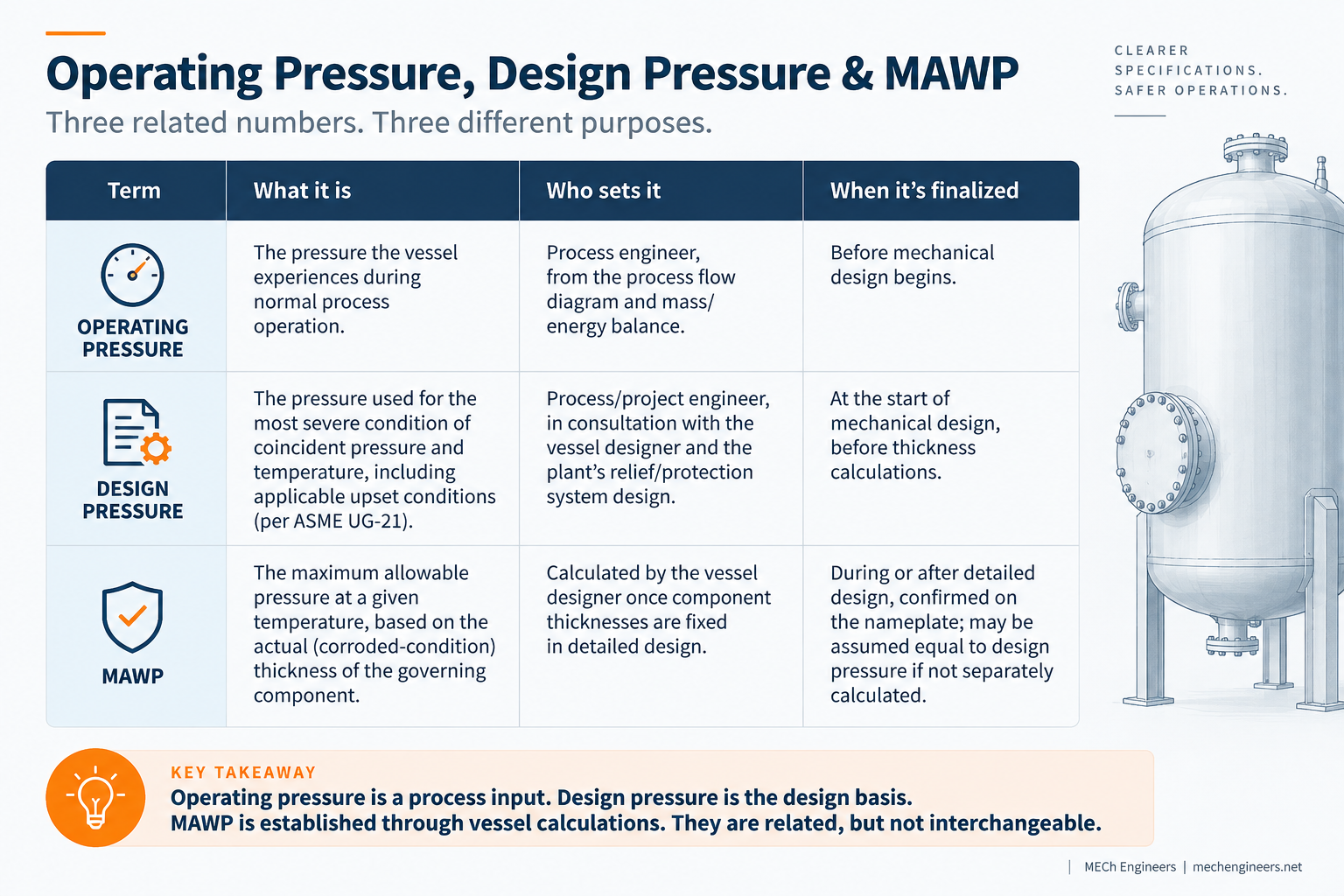
For a buyer writing a specification, the practical takeaway is to state the operating pressure and the relevant upset scenarios and protection philosophy (relief device type, blocked-outlet case, whether a fire case applies) and let the design pressure be derived from that information by the vessel designer, rather than assumed as operating pressure plus an arbitrary flat percentage.
Design Temperature Sets the Material’s Strength, Not Just a Comfort Margin
Design temperature does more work in a vessel calculation than most specifications acknowledge. It isn’t there to confirm the vessel won’t melt. Together with the material specification, it sets the allowable stress value used in the thickness calculation, and that allowable stress generally falls as temperature rises. A carbon steel plate that comfortably carries a given stress at 150°C carries measurably less at 350°C. Specify the wrong design temperature and the thickness calculation is wrong before it starts, regardless of how carefully everything downstream is done.
There’s a related decision that’s easy to miss at the inquiry stage: how much headroom to build into the design temperature above the currently expected operating range. A vessel designed exactly to today’s operating temperature works fine today, but if the process later runs hotter, even temporarily, the vessel may need a formal re-rating or fitness-for-service assessment before it can legally continue in service at the new condition. Specifying a design temperature with reasonable headroom above the expected operating range avoids that cost later, at the price of a marginally thicker (and marginally more expensive) vessel now. Neither choice is automatically correct; it depends on how likely a future temperature change actually is, and how disruptive a re-rating exercise would be for that specific plant.
At the low-temperature end, a separate and genuinely important check applies: the vessel’s Minimum Design Metal Temperature (MDMT). Carbon and low-alloy steels can lose fracture toughness and become susceptible to brittle fracture at sufficiently low metal temperatures, well below the temperature at which the material would otherwise fail structurally under load. ASME Section VIII addresses this through impact-testing requirements and a set of exemption curves (in provisions such as UCS-66) that relate material, thickness, and governing stress to a minimum temperature at which impact testing can be waived.[3] Establishing the correct MDMT for a vessel, and determining whether impact testing or an exemption applies, is a specialist calculation that depends on material grade, section thickness, stress ratio, and the lowest credible metal temperature the vessel will see (including during startup, depressurization, or auto-refrigeration events) — a full treatment is outside the scope of this article, but any vessel with a cold-service, refrigeration, or auto-refrigerating duty should have its MDMT and impact-test basis addressed explicitly in the design rather than assumed to be covered by material selection alone.
Corrosion Allowance Belongs to the Component, Not the Vessel
Corrosion allowance is one of the most frequently named and least well-explained parameters in pressure vessel design. Most descriptions of it stop at “extra thickness added for corrosion,” which is true but incomplete. The harder, more useful question is how much, and the honest answer is that it depends on the fluid, the material, the expected design life, and how easily the component can be inspected or replaced.
A shell in continuous contact with a corrosive process fluid needs an allowance based on the actual corrosion rate for that specific fluid and material combination, over the vessel’s intended design life. A nozzle in the same vessel, if it sees the same fluid but is smaller and structurally more sensitive to reinforcement calculations, may be assigned a different allowance than the shell around it. Non-replaceable internals, which can’t be swapped out during a shutdown the way a gasket or a tray can, sometimes carry a different allowance again, because there’s no practical way to “wait and see” once they’re installed. Treating corrosion allowance as a single number applied uniformly across an entire vessel is a simplification that often either overspends on components that don’t need it or under-protects the one component that does.
The corrosion rate itself should come from process/materials engineering data specific to the fluid and metallurgy involved, not from a generic table. That said, it’s useful to understand the general categories of reasoning that go into the decision:
| Service category | General consideration |
| Well-understood, non-corrosive or mildly corrosive service in a corrosion-resistant alloy (e.g., stainless steel in a clean process fluid) | Corrosion allowance is often minimal or near zero, provided this is a documented engineering decision based on known compatibility, not an oversight |
| General carbon steel service with mild to moderate corrosivity | A modest allowance is typically applied, sized to the expected corrosion rate over the intended design life |
| Known corrosive, erosive, or poorly characterized service | A larger allowance is typically warranted, often supported by corrosion-rate data, coupon testing, or documented plant experience with similar fluids |
These are categories of reasoning, not values to copy onto a datasheet. The correct number for a specific vessel always depends on fluid chemistry, temperature, velocity, and metallurgy data particular to that application. What matters for a buyer reviewing a design basis is whether the fabricator can explain why a given allowance was chosen for a given component, not whether the number matches a table found online. A zero corrosion allowance, documented and justified by material compatibility, is a legitimate engineering decision. An unexamined default number, applied the same way regardless of service, is not.
Why the Ordered Plate Is Thicker Than the “Required” Number
This is a small point that causes a disproportionate amount of buyer confusion. A code calculation produces a minimum required thickness for a given shell or head, based on design pressure, design temperature, material allowable stress, and geometry. That number, on its own, is rarely the thickness that ends up on the fabrication drawing, and the difference is not padding.
Consider the sequence conceptually. The code calculation might produce a minimum required thickness of, say, 11.8 mm for a shell course, before corrosion allowance. Add a corrosion allowance appropriate to the service, say 3 mm, and the true minimum needed is 14.8 mm. Plate doesn’t come in that exact thickness commercially, so the next available standard plate thickness, perhaps 16 mm, is selected. There’s a further detail that rarely makes it into buyer-facing explanations at all: plate materials are supplied against a material specification that permits the actual delivered thickness to run slightly under the nominal ordered thickness within a defined tolerance band. The nominal thickness ordered has to be enough to cover the calculated requirement even after accounting for that under-tolerance.
None of the numbers in that example are meant to represent a real project. The point is the sequence: required thickness, plus corrosion allowance, rounded up to a commercial plate size, checked against plate under-tolerance, arriving at the specified nominal thickness. A buyer who sees a fabricator specify a plate thicker than their own back-of-envelope calculation shouldn’t automatically read that as overbuild or margin-stacking. It’s usually this ordinary, unglamorous sequence playing out as intended.
External Pressure and Vacuum: A Different Failure Mode Entirely
Everything discussed so far assumes the vessel is being pushed outward by internal pressure. Many process vessels also need to be checked for the opposite condition: external pressure, which includes both true external pressure (a jacketed vessel with process pressure in the annulus, for example) and vacuum service, where internal pressure drops below atmospheric.
The failure mode under external pressure is fundamentally different from internal pressure failure. Internal pressure stretches the shell in tension, and a thin shell that’s slightly under-designed for internal pressure tends to fail by yielding or rupture in a relatively predictable way. External pressure compresses the shell, and an under-designed shell under external pressure can fail suddenly by elastic or plastic buckling — a collapse mode that gives little warning and is governed as much by the vessel’s geometry (diameter, unsupported length, and wall thickness together) as by the material’s strength alone. ASME Section VIII, Division 1 addresses this in UG-28 through UG-30, using a design methodology built around geometric charts rather than the direct stress formulas used for internal pressure, because the governing failure mode is instability rather than simple overstress.[4]
For a buyer, the practical implication is that a vessel intended to operate under vacuum, or with a jacket or other external pressure source, needs to be flagged as such at the inquiry stage, not treated as an afterthought to the internal pressure case. It can also change the design in ways that aren’t obvious from the internal-pressure numbers alone: a shell sized comfortably for a moderate internal pressure may need to be thickened, or fitted with stiffening rings, specifically to resist buckling under a vacuum or external-pressure condition that has nothing to do with the internal design pressure.
Nozzle Design and Reinforcement
Nozzle openings are one of the design details most likely to require careful reinforcement calculation and to surface as a point of design revision if not addressed early, because of a straightforward structural reality: every nozzle is a hole cut into a pressure-retaining shell. Cutting that hole removes load-bearing metal from a surface that was sized specifically to carry the design pressure. Left unaddressed, that missing metal creates a local stress concentration that can reduce the effective strength of the vessel at that location. ASME Section VIII requires that the removed area be compensated, either by extra thickness already present in the surrounding shell and the nozzle neck itself, or by additional reinforcement added specifically for that opening, under the area-replacement rules of UG-36 and UG-37, with certain smaller openings potentially exempt under defined conditions.[5] The full calculation is a specialist exercise, better performed by the vessel designer than summarized here, but the underlying logic is worth understanding for anyone reviewing a nozzle schedule.
Two practical distinctions matter more to a buyer than the calculation itself. The first is set-in versus set-on nozzle configuration: whether the nozzle neck passes through the shell wall or sits on top of it, which affects weld geometry, inspection access, and how cleanly the joint can be examined later. The second is the choice between a welded reinforcement pad and an integrally reinforced (or “self-reinforced”) nozzle, where the extra thickness needed for reinforcement is built into the nozzle neck itself rather than added as a separate pad welded around it afterward.
Neither approach is universally correct, and the right choice depends on several factors evaluated together: the local geometry and stress distribution at the opening, whether the service involves cyclic or fatigue-relevant loading, fabrication practicality (including access for welding and post-weld heat treatment where required), inspection and examination access after fabrication, and any applicable code or project-specific requirements. A welded reinforcement pad is generally simpler and less costly to fabricate, and performs adequately across a wide range of standard process applications. Where cyclic pressure or thermal loading is a governing consideration, the fillet weld attaching a pad to the shell introduces a local geometric discontinuity that a designer needs to evaluate for fatigue, and in some such cases an integrally reinforced nozzle — which avoids that particular weld-toe discontinuity — may be the more appropriate choice; in other cyclic-service cases, a properly analyzed and detailed reinforcement pad performs perfectly well. The decision is a case-by-case fatigue and stress evaluation, not a blanket rule that one configuration is disqualified for cyclic service and the other is always superior.
A separate factor is worth raising because it’s so often left until too late in the project: nozzle spacing and orientation. Nozzles placed too close together interact with each other’s reinforcement zones, which can force a design change if it isn’t checked at the layout stage. Piping loads transmitted into the nozzle from connected pipework, not just the vessel’s own internal pressure, are a real structural input that sometimes gets left off an early-stage specification and discovered only once the piping design is further along. Settling the nozzle schedule, spacing, and expected external loads at the general arrangement drawing stage is considerably cheaper than discovering a conflict after fabrication has started.
Choosing Between ASME Section VIII Division 1 and Division 2
This decision is made early in the design process, after the pressure, temperature, and general service conditions are established.
- Division 1 — Design by rules
- Uses prescribed formulas, tables, and established design rules.
- Provides a relatively predictable design, fabrication, and documentation route.
- Commonly used for standard process vessels operating at moderate pressures.
- Generally involves less extensive stress analysis than Division 2.
- Division 2 — Design by analysis
- Includes design-by-rule provisions in Part 4 and design-by-analysis methods in Part 5.
- Requires more detailed, component-specific stress evaluation.
- May involve finite element analysis for complex geometries.
- Requires fatigue evaluation where cyclic loading is relevant.
- Can sometimes produce a thinner or more material-efficient vessel, but savings are not guaranteed.
- Requires greater engineering effort, quality assurance, documentation, and a formal design report.
Which Division Should Be Selected?
- Division 1 is often suitable when the vessel has a conventional design, moderate pressure, and relatively straightforward loading conditions.
- Division 2 may be worth evaluating for:
- High-pressure applications.
- Cyclic or fatigue-sensitive service.
- Complex geometries or significant local stresses.
- Expensive alloys where material savings could offset additional engineering costs.
Key point: Neither division is universally superior. The selection should be based on the vessel’s actual design conditions, stress state, material, geometry, project requirements, and the balance between engineering effort and potential savings.
Supports Aren’t a Styling Choice
Vessel supports (skirts, saddles, support legs, and lugs) tend to get presented as a simple menu: pick the one that matches your vessel orientation. In practice, the choice is driven by a combination of factors that also feed back into the shell design itself, not a separate, standalone decision made after the vessel is otherwise finished.
Orientation is the first factor: a tall vertical vessel with a high length-to-diameter ratio behaves differently under wind and seismic loading than a short, squat horizontal one, and that difference shapes whether a skirt, legs, or lugs make structural sense. A skirt distributes load around the full circumference of the shell and tends to suit tall vertical vessels well; support legs are more common on smaller vertical vessels where a full skirt isn’t justified; horizontal vessels are typically supported on saddles positioned to manage bending stress along the shell’s length; lugs are often used where the vessel needs to be supported from an external structure rather than from grade.
Site conditions matter as much as vessel geometry. Wind loading and seismic input relevant to the vessel’s actual location factor into the support design, and for projects sited in India, this is a real, project-specific input governed by the applicable Indian design standards for wind and seismic loads, not a generic afterthought. The support attachment point also creates local stresses in the shell itself, meaning support design and shell design aren’t fully independent decisions, and foundation or civil coordination needs to happen early enough that the vessel’s support configuration and the foundation design aren’t finalized in isolation from each other.
Inspection, NDT Extent, and Joint Efficiency
It’s common for two quotations covering what looks like a similar vessel to specify noticeably different non-destructive examination scope, and for a buyer to read that difference as one vendor cutting corners. That’s not usually what’s happening. The extent of radiographic, ultrasonic, magnetic particle, or liquid penetrant examination applied to a vessel’s welds is a design-stage decision, governed by the applicable code, and it is directly linked to the joint efficiency value assigned to the weld — which in turn feeds directly into the thickness calculation.
Under ASME Section VIII, Division 1, welded joints are assigned a joint category (based on their location and function) and a joint efficiency factor that depends on the weld type and the extent of radiographic or other examination performed, following the values set out in the Code’s joint efficiency tables such as UW-12.[7] A design based on full radiographic examination of the governing pressure-retaining welds can generally use a higher joint efficiency, and therefore a thinner calculated shell, than the same design based on spot or no radiographic examination. The examination extent and the wall thickness are linked at the calculation stage, not decided independently afterward. A lower NDT scope on one quotation isn’t automatically a lower-quality vessel; it may reflect a different, equally valid combination of joint efficiency and thickness that the buyer should understand rather than assume is inferior — though it is reasonable, and advisable, to ask a fabricator to explain the specific joint efficiency and examination basis used for a given quotation.
Hydrostatic Testing: What It Verifies and How the Test Pressure Is Set
Hydrostatic testing serves a different, final-verification purpose from design-stage calculations and in-process examination. The completed vessel is filled with water and pressurized to a defined test pressure to confirm mechanical integrity and check for leaks before it is placed into service.
Under the current edition provisions of ASME Section VIII, Division 1, UG-99(b), the standard hydrostatic test pressure for a vessel designed for internal pressure is at least 1.3 times the MAWP, multiplied by the lowest ratio of the material’s allowable stress at test temperature to its allowable stress at design temperature (this ratio is intended to prevent the test itself from over-stressing a material whose allowable stress changes significantly with temperature).[8] This 1.3 multiplier reflects a design margin of 3.5 introduced in more recent Code editions; vessels designed under earlier Code editions, prior to the relevant addenda, used a 1.5 multiplier tied to the design margin in force at that time. The specific multiplier and any related adjustment factors applicable to a given vessel should be confirmed against the Code edition governing that project, since the requirement has been revised historically and the applicable edition depends on the contract and jurisdiction.
What matters for a buyer is understanding that the hydrotest isn’t a formality tacked onto the end of fabrication. It’s the final, physical confirmation that the design and fabrication together deliver the strength the calculations claimed, performed after all fabrication and required examination (other than any inspection specifically required after the hydrotest) has been completed.
Regulatory Considerations for Vessels Manufactured for or Installed in India
- ASME Section VIII is not India’s statutory framework
- ASME Section VIII is an internationally recognized design and fabrication code.
- It may be used as the vessel’s design basis, but it does not automatically satisfy every Indian regulatory requirement.
- Additional requirements depend on the vessel’s service, application, destination, and project specification.
- Indian Boiler Regulations (IBR)
- IBR primarily applies to boilers and specified boiler- or steam-related equipment.
- Depending on the applicable pressure and capacity thresholds, this may include:
- Boilers
- Steam receivers
- Steam separators
- Certain heat exchangers
- Other equipment associated with steam service
- IBR is not a universal requirement for every pressure vessel.
- Applicability should be confirmed with the relevant authority for the specific equipment and service.
- PESO requirements
- Petroleum and Explosives Safety Organisation (PESO) approval may apply to equipment handling:
- Petroleum products
- Explosive substances
- Specified hazardous materials
- These requirements are service-specific and depend on the applicable legal and safety framework.
- Petroleum and Explosives Safety Organisation (PESO) approval may apply to equipment handling:
- National Board registration and ‘R’ Stamp
- National Board registration and the ‘R’ Stamp are associated primarily with repair and alteration activities under jurisdictions that have adopted the National Board Inspection Code.
- They may be relevant for North American projects or where the contract specifically requires them.
- They are not, by themselves, part of India’s general statutory requirements for pressure vessels installed in India.
- Practical compliance considerations
- Confirm requirements based on:
- Equipment type
- Process fluid and service
- Installation location
- Destination country
- Applicable statutory authority
- Client, EPC, and licensor specifications
- Buyers should verify the requirements with the relevant regulatory authority or a qualified compliance specialist.
- Confirm requirements based on:
- MECh Engineers’ certifications and approvals
- MECh Engineers’ published information lists capabilities and certifications including ASME ‘U’ and ‘U2’ Stamps, NBBI ‘R’ Stamp accreditation, National Board registration, IBR-related approvals, PESO/CCOE-related approvals, PED compliance, and ISO management-system certifications.
- Buyers should confirm the current validity, scope, and applicability of each certification directly with MECh Engineers before relying on it for a specific project.
What to Specify at Inquiry Stage, and What to Leave to the Fabricator’s Engineers
Everything above points toward a practical question: when writing an inquiry or reviewing a proposal, what actually needs to be defined by the buyer or process engineer, and what is reasonable to leave to the fabricator’s design team? Getting this split wrong in either direction causes real problems. Under-specifying leaves too much open to assumption and invites clarification cycles during quotation. Over-specifying, by dictating fabrication-level decisions the buyer isn’t positioned to make well, can eliminate design options that would have served the application better.
| The buyer/process engineer should specify | The fabricator’s engineering team should determine |
| Operating pressure and temperature, including expected variability | Design pressure margin, based on relief system philosophy and credible upset scenarios |
| Fluid/service description and known corrosivity, fouling, or cyclic-loading behavior | Exact corrosion allowance per component, and material selection where not already fixed by process requirements |
| Expected design life and inspection interval expectations | Nominal plate thickness selection, accounting for commercial sizes and material tolerance |
| Applicable codes, jurisdiction, and any client-specific engineering standards | Specific nozzle reinforcement method (pad versus integral) for each connection, based on stress and fatigue evaluation |
| Nozzle functional requirements: size, service, connected piping, and expected external loads | Examination/NDT plan and associated joint efficiency, within the range the governing code permits |
| Site location and applicable wind/seismic loading data; whether vacuum or external-pressure service applies | Support structural detailing and external-pressure/buckling design, consistent with vessel orientation and site data supplied |
Even where a decision is reasonably left to the fabricator’s judgment, the buyer should still expect it to be explained. A design basis document that states the corrosion allowance chosen for each major component, the joint efficiency and examination basis used, and the reasoning behind the design pressure margin is a sign of a fabricator engineering the vessel deliberately, rather than defaulting to a template.
A few specification mistakes show up often enough to be worth naming directly. Specifying design temperature as exactly equal to current operating temperature, with no allowance for future process changes, is one. Leaving the nozzle schedule incomplete or provisional at inquiry stage, when it’s one of the parameters most likely to trigger a design revision later, is another. Treating corrosion allowance as a single number to be applied everywhere, without distinguishing shell, nozzles, and internals, is a third. Omitting whether the vessel needs to be checked for vacuum or external pressure — because it wasn’t the “main” design case — is a fourth, and one that’s easy to overlook precisely because it isn’t the headline pressure number on the datasheet. None of these are dramatic errors, but each one reliably produces avoidable delay or cost somewhere later in the project.
Where This Leaves the Decision
The parameters on a pressure vessel datasheet aren’t independent settings. Design pressure shapes the thickness calculation, which interacts with corrosion allowance and material selection, which determines the plate that gets ordered, which constrains how nozzles are reinforced and how external-pressure or vacuum conditions are checked, which in turn feeds into the support design and the inspection regime that verifies the whole thing was built the way it was designed. Treating any one of these as a checkbox, disconnected from the rest, is how specifications end up incomplete and how quotations for what looks like “the same vessel” end up looking inconsistent.
The more useful way to approach a custom vessel, whether writing the inquiry or reviewing the proposal that comes back, is to expect the reasoning behind each number, not just the number itself. A fabricator who can explain why a given design pressure margin, corrosion allowance, or nozzle reinforcement approach was chosen for a specific application is doing the engineering the application actually needs, rather than applying a template and hoping it fits.
MECh Engineers has been designing and manufacturing custom-engineered pressure vessels, reactors, heat exchangers, and related process equipment since 1986, working in materials ranging from carbon and stainless steel through duplex, super duplex, Hastelloy, Inconel, and titanium, under ASME ‘U’ and ‘U2’ Stamp, NBBI ‘R’ Stamp, IBR, and CCOE/PESO approvals. If you have a specific application, a set of design conditions, or a material and nozzle configuration you need to work through, get in touch with MECh Engineers to discuss it directly with the engineering team.